
4. Networking#
4.1. Linux Networking#
Overview of network protocols and TCP/IP in Linux.
Network configuration in Linux.
Netplan configuration on Ubuntu servers.
Network settings in Red Hat via NetworkManager.
Network troubleshooting tools:
ping,traceroute,tcpdump.Network calculation using
ipcalc.Network applications and services.
Network traffic sniffing with
tcpdump.Installation and configuration of the
lighttpdweb server.Port tunneling using SSH.
4.2. Computers on the Internet#
Network communication enables data transmission, file transfer, and remote application management between interconnected computer systems. Networks are structured into independent, functional layers implemented on each system:
Each layer performs a specific set of tasks and provides services to adjacent layers (above and below).
Inter-layer communication adheres to defined rules and procedures known as protocols.
Data is processed sequentially through the layers from top to bottom before transmission.
At the bottom layer, physical systems communicate by transmitting and receiving network datagrams across hardware infrastructure, including cables, switches, and routers.
[ Host Machine A: Application Layer ]
                |
                v
[ Transport / Internet / Link Layers ]
                |
                v
   ( Physical Infrastructure )
   (  Cables / Switches / Routers  )
                |
                v
[ Transport / Internet / Link Layers ]
                |
                v
[ Host Machine B: Application Layer ]
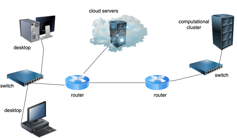
Accessible Image Description:
Overview: A network diagram illustrating inter-computer communication through connected infrastructure.
Setup: The diagram shows terminal nodes (computers) connected via physical cabling through intermediate networking hardware including network switches and routers.
Key Takeaways: Data flows down through protocol layers on the source node, across network hardware, and up through protocol layers on the destination node.
4.3. TCP/IP 5-Layer Protocol Suite#
+-------------------------------------------------------------------+
| 5. Application Layer: SSH, FTP, HTTP, SMTP                       |
+-------------------------------------------------------------------+
| 4. Transport Layer: TCP, UDP, Port Numbers                        |
+-------------------------------------------------------------------+
| 3. Internet Layer: IP Addresses, Subnets, Routing                 |
+-------------------------------------------------------------------+
| 2. Link Layer: Ethernet, MAC Addresses, Network Switch            |
+-------------------------------------------------------------------+
| 1. Physical Layer: Network Interface Cards (NIC), Cabling, Signal |
+-------------------------------------------------------------------+
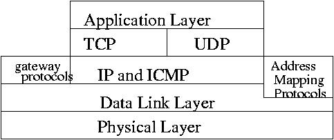
Accessible Image Description:
Overview: Architectural diagram displaying the 5-layer TCP/IP protocol stack model.
Setup: Layers are arranged vertically from Layer 5 (Application) down to Layer 1 (Physical), identifying key protocols and hardware at each tier.
Key Takeaways: Each layer performs dedicated communication tasks, passing formatted data payloads to adjacent layers.
4.3.1. TCP/IP Protocol Layers and Tasks#
TCP/IP Protocol Layer |
Core Responsibilities |
|---|---|
5. Application Layer |
Data segmentation by the application into Maximum Transmission Unit (MTU) segments. Typical MTU is 1.5 KB, containing the data payload plus 40 bytes for TCP and IP headers. |
4. Transport Layer |
Connection management, error control, traffic flow control, and port addressing for application delivery. |
3. Internet Layer |
Host addressing across network interfaces and packet routing across interconnected subnets. |
2. Link Layer |
Local subnet communication via switches. Uses unique Media Access Control (MAC) addresses (e.g., |
1. Physical Layer |
Hardware devices responsible for converting frames into electronic, optical, or radio signals across physical transmission media. |
4.4. OSI 7-Layer Network Stack Model#
+-------------------------------------------------------------------+
| 7. Application Layer (Network Services & User Interfaces)         |
+-------------------------------------------------------------------+
| 6. Presentation Layer (Data Formatting, Encryption, Compression)  |
+-------------------------------------------------------------------+
| 5. Session Layer (Session Establishment, RPC Management)          |
+-------------------------------------------------------------------+
| 4. Transport Layer (End-to-End Reliability, Error Recovery)       |
+-------------------------------------------------------------------+
| 3. Network Layer (Logical Addressing, Routing Path Selection)     |
+-------------------------------------------------------------------+
| 2. Data Link Layer (Physical Addressing, Framing, Media Access)   |
+-------------------------------------------------------------------+
| 1. Physical Layer (Bit Transmission, Hardware Interfaces)         |
+-------------------------------------------------------------------+
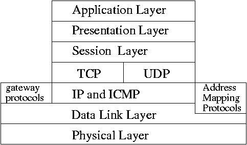
Accessible Image Description:
Overview: Architectural diagram depicting the Open Systems Interconnection (OSI) 7-layer reference model.
Setup: A stacked vertical layout illustrating the Application, Presentation, Session, Transport, Network, Data Link, and Physical layers.
Key Takeaways: Demonstrates the theoretical 7-layer segmentation for network functions, highlighting upper-level processing layers (5–7) that handle application interaction, encoding, and session persistence.
4.4.1. OSI Upper Layers Summary#
OSI Protocol Layer |
Core Responsibilities |
|---|---|
7. Application Layer |
Data segmentation by applications into standard payload sizes. |
6. Presentation Layer |
Data encryption, compression, syntax formatting, and encoding/decoding. |
5. Session Layer |
Establishes, maintains, synchronizes, and terminates interactive sessions between systems. |
4.5. TCP/IP and Kernel Integration#
+-------------------------------------------------------------------+
| USER SPACE: Application Layer (HTTP, SSH, FTP)                    |
+-------------------------------------------------------------------+
==================== Operating System Boundary ======================
+-------------------------------------------------------------------+
| KERNEL SPACE: Transport Layer (TCP, UDP Protocol Engines)         |
+-------------------------------------------------------------------+
| KERNEL SPACE: Internet Layer (IP Routing, ICMP, Subnet Masking)   |
+-------------------------------------------------------------------+
| KERNEL SPACE: Link Layer (NIC Device Drivers, ARP, Frame Buffers) |
+-------------------------------------------------------------------+
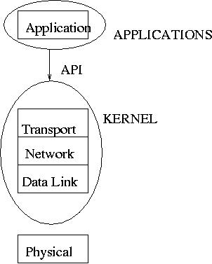
Accessible Image Description:
Overview: Diagram showing where network stack components reside within Linux OS architecture.
Setup: Divides networking responsibilities between User Space (Application layer) and Kernel Space (Transport, Internet, and Link layers).
Key Takeaways: The Linux operating system kernel directly manages lower-level networking protocols, abstracting physical driver and network handling away from user applications.
4.6. Packet Encapsulation#
Data is transmitted across networks using packet encapsulation, ultimately structured as physical Ethernet frames.
+-------------------------------------------------------------------+
| Ethernet Frame Header                                             |
|   +-----------------------------------------------------------+   |
|   | IP Packet Header                                          |   |
|   |   +---------------------------------------------------+   |   |
|   |   | TCP Segment Header                                |   |   |
|   |   |   +-------------------------------------------+   |   |   |
|   |   |   | User Application Payload / Data           |   |   |   |
|   |   |   +-------------------------------------------+   |   |   |
|   |   +---------------------------------------------------+   |   |
|   +-----------------------------------------------------------+   |
| Ethernet Frame Trailer (FCS Checksum)                             |
+-------------------------------------------------------------------+
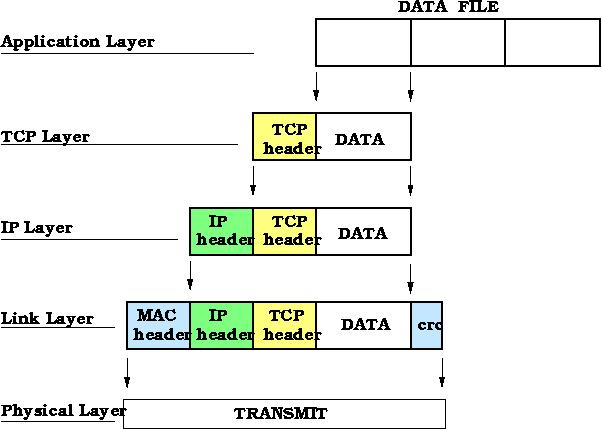
Accessible Image Description:
Overview: Conceptual diagram illustrating packet encapsulation.
Setup: Concentric nested headers showing user data wrapped inside TCP, IP, and Ethernet frame control structures.
Key Takeaways: As application data travels down the network stack, each layer prepends control metadata required for transport, logical addressing, and hardware frame delivery.
4.7. Host-to-Host Communication via TCP/IP#
[ Host A Application ]                               [ Host B Application ]
          |                                                    ^
          v                                                    |
[ Host A TCP/IP Stack ] === ( Physical Network Link ) ===> [ Host B TCP/IP Stack ]
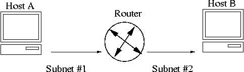
Accessible Image Description:
Overview: High-level sequence diagram showing end-to-end communication between two host computers across a network link.
Setup: Illustrates logical peer-to-peer communications at matching protocol layers between Host A and Host B.
Key Takeaways: Protocols at corresponding layers logically interact, while physical data movement occurs vertically down through the sending host’s stack and up the receiving host’s stack.
Host A (Sender)                                Host B (Receiver)
+-------------------+                          +-------------------+
| Application Layer | === Logical Channel ===> | Application Layer |
| Transport Layer   |                          | Transport Layer   |
| Internet Layer    |                          | Internet Layer    |
| Link Layer        | === Physical Medium ===> | Link Layer        |
+-------------------+                          +-------------------+
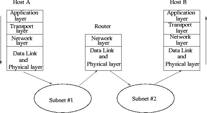
Accessible Image Description:
Overview: Detailed layout of host-to-host TCP/IP interaction showing protocol abstraction across physical links.
Setup: Side-by-side comparative stack diagram mapping encapsulation on Host A and decapsulation on Host B.
Key Takeaways: Physical data transmission occurs through underlying network media, while user processes communicate via abstracted logical protocol channels.
4.8. Wired Connection Checkup (Lab Exercise)#
To verify whether a network interface is physically connected to a switch and check its operational speed, use the ethtool command.
Install
ethtoolon Ubuntu:
sudo apt update && sudo apt install ethtool
List active network interfaces using
ip address showor its shorthand version:
ip a
Query interface properties for the primary Ethernet device (
enp0s3):
/sbin/ethtool enp0s3
In virtualized environments (such as VDI or virtual machines), hardware parameter queries may return link detection without showing fixed hardware negotiation properties:
Speed: Unknown!
Duplex: Unknown!
Link detected: yes
On bare-metal physical hardware, expected output includes hardware link negotiation details:
Speed: 1000Mb/s
Duplex: Full
Link detected: yes
This output confirms that the network cable is connected, running at 1 Gbps full-duplex mode.
4.9. Network IP Configuration Overview#
Network interface configurations generally use one of two methods:
Static Configuration: IP address, subnet mask, default gateway, hostname, and Domain Name System (DNS) servers are manually specified on the host.
Dynamic Configuration (DHCP): Network settings are leased automatically from a Dynamic Host Configuration Protocol server.
[ Client Host ]                                   [ DHCP Server ]
       |                                                 |
       | --- 1. DHCPDISCOVER (Broadcast) --------------> |
       |                                                 |
       | <-- 2. DHCPOFFER (Unicast/Broadcast) ---------- |
       |                                                 |
       | --- 3. DHCPREQUEST (Broadcast) ---------------> |
       |                                                 |
       | <-- 4. DHCPACK (Unicast) ---------------------- |
       v                                                 v
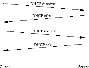
Accessible Image Description:
Overview: Sequence diagram showing the four-step Dynamic Host Configuration Protocol (DHCP) handshake process.
Setup: A vertical time sequence illustrating message exchanges between a client requesting configuration and a responding DHCP server.
Key Takeaways: Dynamic network configuration relies on the DHCP sequence (Discover, Offer, Request, Acknowledge) to assign IP addresses, subnet masks, and default gateways automatically.
4.10. Network Configuration Tools Across Linux Distributions#
Configuration Tool / Script |
|
Netplan ( |
|---|---|---|
Traditional Debian / Red Hat |
Desktop / Modern Enterprise Linux |
Ubuntu Server Systems |
File: |
Commands: |
Configuration file: |
File: |
System File Path: |
Application Command: |
Command: |
Reload Command: |
4.11. Deploying a Virtual Machine for Exercises#
Shut down the existing
kvm1VM and clone it to createnetplan:
virsh shutdown kvm1
virt-clone -o kvm1 -n netplan -f /home/hostadm/KVM/netplan.qcow2
Start the new
netplanVM and open its console:
virsh start netplan
virsh console netplan
Update the host name inside
/etc/hostname.Reset the machine ID by running the system script inside the VM:
./vm_id_reset.sh
Remove default cloud-init SSH restriction files if present:
rm /etc/ssh/sshd_config.d/60-cloudimg-settings.conf
Reboot the VM:
reboot
4.12. Configuring Network Settings on Ubuntu Server with Netplan#
Check existing IP parameters on the
netplanVM:
ip addr
Switch to root privileges:
sudo -s
Configure static IP address
192.168.122.222by editing/etc/netplan/00-installer-config.yaml:
---
network:
  version: 2
  renderer: networkd
  ethernets:
    enp1s0:
      dhcp4: false
      addresses:
        - 192.168.122.222/24
      routes:
        - to: default
          via: 192.168.122.1
      nameservers:
        addresses: [192.168.122.1]
Install and run YAML syntax validation tools:
apt install yamllint
yamllint /etc/netplan/00-installer-config.yaml
Apply the network configuration:
netplan apply
Verify the updated configuration on interface
ens3(orenp1s0):
ip addr
Confirm gateway route settings:
ip route show
(Expected output includes: default via 192.168.122.1)
4.13. Cloning the rocky10 VM#
(If rocky10-1 is already available from previous exercises, skip cloning and proceed to network configuration).
Stop
rocky10and clone it:
virsh list
virsh stop rocky10
virt-clone -o rocky10 -n rocky10-1 -f /home/hostadm/KVM/rocky10-1.qcow2
Start
rocky10-1and attach to the console:
virsh start rocky10-1
virsh console rocky10-1
Install system tools and update the machine hostname to
rocky10-1:
sudo dnf install -y dbus-tools
Reset unique system identifiers:
sudo rm -f /etc/machine-id
sudo dbus-uuidgen --ensure=/etc/machine-id
sudo dbus-uuidgen --ensure
sudo dhclient -r enp1s0
Reboot the VM:
reboot
4.14. Network Configurations on Red Hat Enterprise Linux / Rocky Linux#
Red Hat systems utilize nmcli to command the NetworkManager service.
Log into the console of
rocky10-1:
virsh start rocky10-1
virsh console rocky10-1
Read IP interface information:
ip addr show enp1s0
Test initial connectivity to
netplan:
ping -c 3 192.168.122.222
Elevate privileges to root:
sudo -s
List active NetworkManager connections:
nmcli conn show
Display device properties for
enp1s0:
nmcli dev show enp1s0
Create a static network profile named
eth_static:
nmcli con add type ethernet con-name eth_static ip4 192.168.122.126/24 gw4 192.168.122.1 ipv4.dns 192.168.122.1
Activate
eth_static:
nmcli con up eth_static
nmcli conn show
ip addr show enp1s0
Modify an existing static connection address to
192.168.122.125:
nmcli con modify eth_static ipv4.addresses 192.168.122.125/24
nmcli con up eth_static
ip addr show enp1s0
4.14.1. Alternative Configuration File Method#
nmcli generates configuration profiles under /etc/NetworkManager/system-connections/. You can manually edit these files and apply changes:
systemctl restart NetworkManager
nmcli con up eth_static
4.14.2. Reverting to Dynamic DHCP#
To restore automatic network addressing, reactivate the DHCP profile:
nmcli conn up "Wired connection 1"
4.15. Internet Control Message Protocol (ICMP)#
ICMP is deployed across end-hosts and routers to perform:
Datagram processing status reporting.
Routing diagnostics and connectivity verification.
Diagnostic error reporting.
4.15.1. Command Diagnostic 1: ping#
[ Source Host ]                                   [ Target Host ]
       |                                                 |
       | --- ICMP Echo Request (Type 8) ---------------> |
       |                                                 |
       | <-- ICMP Echo Reply (Type 0) ------------------ |
       v                                                 v
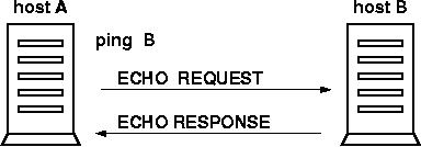
Accessible Image Description:
Overview: Flow diagram of ICMP Echo Request and Reply mechanism used by the
pingutility.Setup: Shows an origin host transmitting an echo request message to a remote host and receiving an echo reply message.
Key Takeaways: The
pingcommand verifies network reachability and measures round-trip time by issuing ICMP echo requests and awaiting replies.
4.15.1.1. Verification Exercise:#
ping -c 5 capone.rutgers.edu
ping -c 5 engsoft.rutgers.edu
ping -c 5 google.com
4.15.2. Command Diagnostic 2: traceroute#
traceroute tracks network pathways by leveraging the Time to Live (TTL) packet field. Intermediate routers decrement TTL by 1; when TTL reaches 0, the router returns an ICMP “Time Exceeded” message.
[ Source Host ] ---> [ Router 1 (TTL=29) ] ===> (ICMP Time Exceeded returned)
[ Source Host ] ---> [ Router 2 (TTL=28) ] ===> (ICMP Time Exceeded returned)
[ Source Host ] ---> [ Target Host (TTL=30-N)] ===> (Destination ICMP Response)
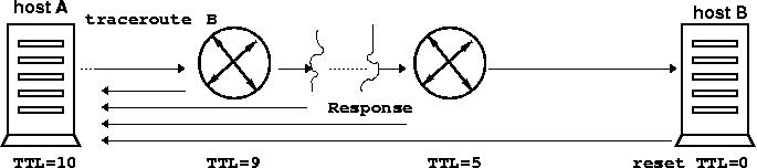
Accessible Image Description:
Overview: Diagram explaining the operating mechanism of the
traceroutenetwork diagnostic tool.Setup: Shows decremental Time To Live (TTL) values assigned to outgoing IP packets by the routers. ICMP Time Exceeded messages are triggered at TTL=0.
Key Takeaways:
tracerouteidentifies each router hop along the path to a destination host by systematically analyzing ICMP expiration responses.
4.15.2.1. Verification Exercise:#
sudo apt install traceroute
sudo /usr/sbin/traceroute -I capone.rutgers.edu
sudo /usr/sbin/traceroute -I engsoft.rutgers.edu
sudo /usr/sbin/traceroute -I google.com
4.16. Subnets and Routing Fundamentals#
[ Host B (Subnet 1) ]
         |
         X <-- Missing Default Gateway Route
         |
    [ Router ]
     /      \
    /        \
[ Host A ]  [ Host C (Subnet 2) ]
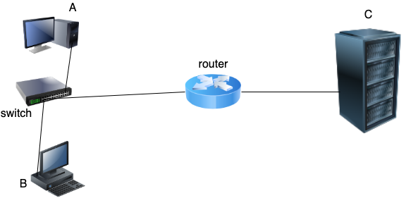
Accessible Image Description:
Overview: Network topology diagram illustrating a routing failure due to missing gateway configurations.
Setup: Host A, Host B, and Host C are connected via a central router across subnets, with Host B lacking a default gateway definition.
Key Takeaways: Communication across separate subnets requires correctly configured default gateways on participating host machines.
4.16.1. Network Calculation Principles#
Devices attached to the same switch share a local subnet and communicate directly via MAC layer delivery.
Traffic destined for external subnets requires routing through a default gateway.
Subnet masks differentiate the network prefix from host identifiers.
Parameter |
Decimal Notation |
Binary Form |
|---|---|---|
IP Address |
|
|
Subnet Mask |
|
|
Network Address |
|
|
Network Address: Lowest address within subnet bounds (
192.168.5.0).Broadcast Address: Highest address within subnet bounds (
192.168.5.255).Usable Host Capacity: \(2^8 - 2 = 254\) usable host IPs (
192.168.5.1to192.168.5.254).
4.17. IP Calculator Exercises (ipcalc)#
Install
ipcalc:
sudo apt install ipcalc
Calculate network boundaries using CIDR or dotted decimal notation:
ipcalc 192.168.5.0/255.255.255.0
ipcalc 192.168.5.0/24
Analyze subnetting for split network blocks:
ipcalc 192.168.5.0/25
ipcalc 192.168.5.128/25
(Notice that 192.168.5.5 resides within the lower /25 subnet, whereas 192.168.5.250 falls into the upper /25 subnet).
4.18. Network Applications: ssh, sftp, scp, rsync#
Determine the target IP address of
netplan:
virsh domifaddr netplan
Append entry to
/etc/hosts:
192.168.122.222 netplan
Generate an SSH keypair on your desktop:
ssh-keygen -t rsa
Transfer public keys using interactive
sftp:
sftp netplan
sftp> cd .ssh
sftp> lcd .ssh
sftp> put id_rsa.pub authorized_keys
sftp> quit
Automate key passphrase management using
ssh-agent:
exec ssh-agent $SHELL
ssh-add
Execute remote commands directly over SSH:
ssh netplan "uname -a"
Copy files remotely using
scpandrsync:
# Copy file from remote to local
scp netplan:/etc/hosts .

# Copy local file to remote home directory
touch somef.txt
scp somef.txt netplan:/home/$USER

# Copy directory recursively
scp -r /etc netplan:

# Synchronize directories via rsync
mkdir -p dir1/dir2/dir3
rsync -avz dir1 netplan:/home/$USER
4.19. Data Transfer via Netcat (netcat / ncat)#
Step |
Ubuntu Server ( |
Red Hat / Rocky Linux ( |
|---|---|---|
1. Tool Installation |
|
|
2. UDP Stream Test |
|
|
3. File Transfer |
|
|
4. Archive Stream |
|
|
4.20. Network Traffic Sniffing with tcpdump#
Install
tcpdumponnetplan:
sudo apt install tcpdump
Capture traffic on interface
enp1s0:
sudo tcpdump -v -n -i enp1s0
Filter capture for specific protocol and IP address:
sudo tcpdump -v -n -i enp1s0 host 192.168.122.126 and proto \icmp
Capture payload data for specific incoming destination ports:
sudo tcpdump -i enp1s0 src host 192.168.122.126 and dst port 8080 -A
4.21. Web Server Deployment (lighttpd)#
Install
lighttpdonnetplan:
sudo apt install lighttpd
Enable directory browsing by editing
/etc/lighttpd/lighttpd.conf:
dir-listing.activate = "enable"
Restart web service:
sudo systemctl restart lighttpd
Populate document root directory (
/var/www/html):
cd /var/www/html
sudo apt download lua5.4
sudo dpkg -X lua5.4_5.4.8-1build1_amd64.deb LUA
sudo rm -f index.lighttpd.html
Retrieve data recursively from client host:
mkdir DOWNLOADS && cd DOWNLOADS
wget http://192.168.122.222/lua5.4_5.4.8-1build1_amd64.deb
wget --recursive -nH http://192.168.122.222/
4.22. SSH Local Port Tunneling#
Forward local client port 8080 to web port 80 on the target VM across an encrypted SSH connection:
ssh -L 8080:192.168.122.222:80 user@desktop-host
Access the forwarded remote service in your local Web Browser:
http://localhost:8080/